 |
| March 28, 2017 | Volume 13 Issue 12 |
Designfax weekly eMagazine

Archives
Partners
Manufacturing Center
Product Spotlight
Modern Applications News
Metalworking Ideas For
Today's Job Shops
Tooling and Production
Strategies for large
metalworking plants
Sheet metal design guide
If you're looking for a basic guide to sheet metal design, especially when using a third-party manufacturing partner, this one from Xometry will serve your needs well.
Overview
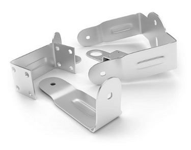
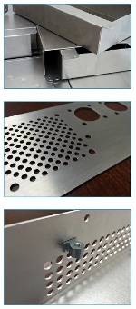
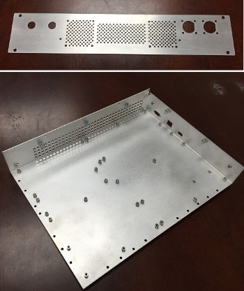 Sheet metal fabrication is the process of forming parts from a metal sheet by punching, cutting, stamping, and/or bending. 3D CAD files are converted into machine code, which controls a machine to precisely cut and form the sheets into the final part. Sheet metal parts are also known for their durability, which makes them great for end-use applications (e.g., chassis). Parts used for low-volume prototypes and high-volume production runs are most cost effective due to large initial set-up and material costs.
Because parts are formed from a single sheet of metal, designs must maintain a uniform thickness. Be sure to follow design requirements and tolerances in this guide to ensure parts fall closer to design intent.
---------------
Tolerances
General Tolerances
- Laser cutting up to 53? x 121? (1.35m x 3.07m) (+pass thru)
- Plasma cutting up to 1/2" (12.7mm) thick plate
- Waterjet Cutting:
- Tilting waterjet head with 4 or 5-axis CNC control
- Waterjet cutting up to +/- 0.004" (+/- 0.1mm) accuracy
- Waterjet cut more than 4? (101.6mm) sheet/plate metal
- Hydraulic Brakes:
- 14 gauge mild steel capacity
- 10? length
- Fingers from 3? to 6?
- Magnetic Brakes:
- 6 tons of magnetic pull across entire beam
- 5/8? minimum reverse bend
- 48? 16 gauge mild steel capacity
- 2" (50.8mm) diameter hole punching capacity
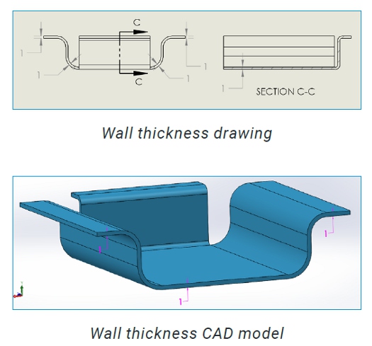
Wall Thickness
Parts must maintain a uniform wall thickness throughout their entirety. Generally, Xometry is capable of manufacturing sheet metal parts up to 1/4" (6.35mm) in thickness, but this tolerance mainly depends on the geometry of the part.
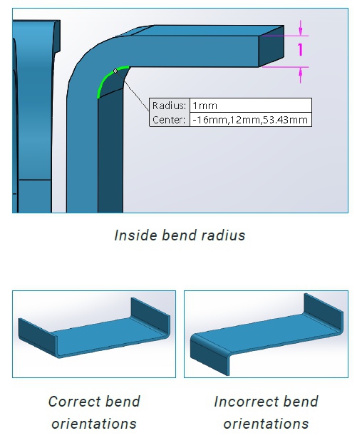
Bends:
Sheet metal brakes are used to bend material into a part's desired geometry. Bends in the same plane should be designed in the same direction to avoid part reorientation, which will save both money and time. Keeping a consistent bend radius will also make parts more cost effective. Small bends to large, thick parts tend to become inaccurate, so they should be avoided if possible.
Dimensions
To prevent parts from fracturing or having distortions, make sure to keep the inside bend radius at least 1 material's thickness.
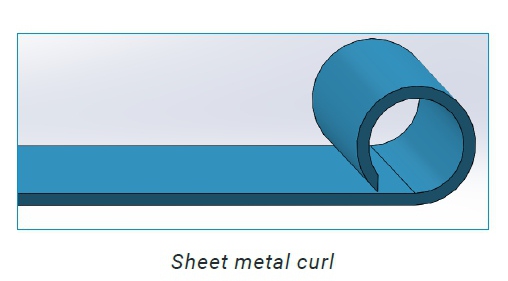
Curls:
Dimensions
Outside radius of curls must be at least 2 times the material's thickness.
Clearances:
Holes should be placed away from the curl at least a distance of the radius of the curl plus the material's thickness. Bends should be at least 6 times the material's thickness plus the radius of the curl.
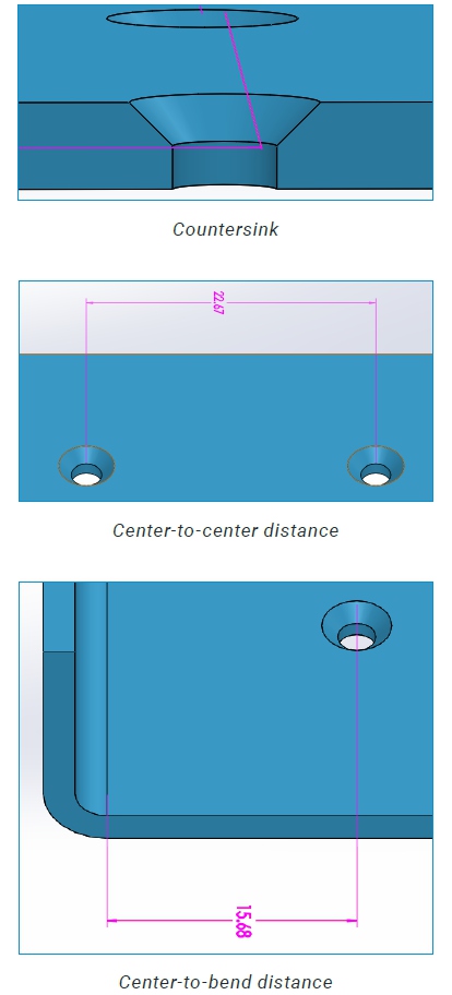
Countersinks:
Dimensions
The maximum depth a countersink may have is 3.5 times the material's thickness.
Clearances
Countersinks must be at least 8 times the material thickness from each other, 4 times the material's thickness from an edge, and 3 times the material's thickness from a bend.
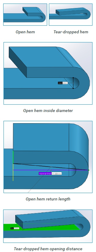
Hems:
Hems are folds to the edge of a part to create a rounded, safe edge. Hems may be open, flat, or tear-dropped, and tolerances depend on the hem's radius, material thickness, and features near the hem.
Note: Flat hems risk fracturing the material at the bend. They should be avoided if possible.
Dimensions
For open hems, minimum inside diameter is equal to the material thickness (larger diameters tend to lose circular shape), and the return length is at least 4 times the material's thickness. Tear-dropped hems must maintain an inside diameter of at least 1 material's thickness, an opening of at least 1/4 the material's thickness, and return length is also 4 times the material's thickness.
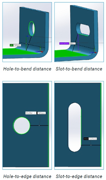
Holes and Slots:
Dimensions
Keep hole and slot diameters at least as large as material thickness. Higher strength materials require larger diameters
Clearances
Holes and slots may become deformed when placed near a bend. The minimum distance they should be placed from a bend depends on the material thickness, the bend radius, and their diameter. Be sure to place holes away from bends at a distance of at least 2.5 times the material's thickness plus the bend radius. Slots should be placed 4 times the material's thickness plus the bend radius away from the bend.
Be sure to place holes and slots at least 2 times the material's thickness away from an edge to avoid a "bulging" effect.
Holes should be placed at least 6 times the material's thickness apart.
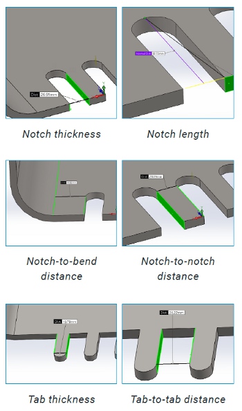
Notches and Tabs:
Dimensions
The minimum thickness a notch must maintain is at least 0.04" (1mm) or the material's thickness, whichever is greater; the length must be no larger than 5 times its width. Tabs must be at least 0.126" (3.2mm) thick, or 2 times the material's thickness, whichever is greater; the length must also be no larger than 5 times its width.
Clearances
Notches must be at least 1/8" (3.175mm) away from each other. For bends, notches must be at least 3 times the material's thickness plus the bend radius. Tabs must have a minimum distance from each other of 0.04" (1mm) or the material's thickness, whichever is greater.
---------------
Features
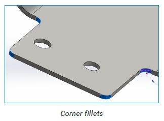
Corner Fillets
Sheet metal parts may have sharp corners, but designing a fillet of 1/2 the material's thickness will make parts more cost effective.
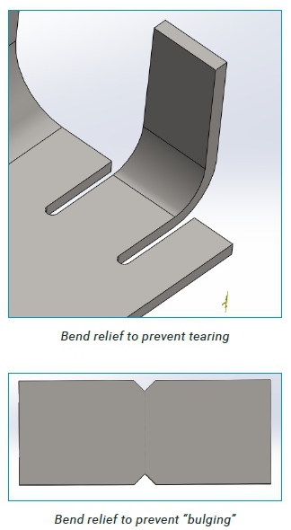
Relief Cuts
Relief cuts help parts fall closer to design intent to avoid "overhangs" and tearing at bends. Overhangs become more prominent for thicker parts with a smaller bend radius, and may even be as large as 1/2 the material's thickness. Tearing may occur when bends are made close to an edge.
Dimensions
Relief cuts for bends must be at least one material's thickness in width, and must be longer than the bend radius.
---------------
Finishes and Post-Processing
Xometry offers sheet metal parts in a wide array of materials including:
- Aluminum
- Stainless steel
- Bronze/Brass
- Copper
- Steel
To further customize parts, Xometry offers post-processing options to add to sheet metal parts such as:
- Bead blasting
- Plating
- Welding
- Inserts
- Other custom finishes upon request
---------------
Resources at Xometry
Online Instant Quoting
- Web: Upload your CAD file at get.xometry.com/quote
- CAD: Download the free Xometry Add-In for SOLIDWORKS: xometry.com/solidworks
- Accepted File Types: .stl, .step, .stp, .iges, .igs, .x_t, .x_b, .sldprt, .ipt, .3dxml, .prt, .sat, .cgr, .3dm, .catpart (max file size: 300MB)
- Capabilities: CNC Machining, Sheet Metal Fabrication, 3D Printing, Urethane Casting
Live Engineering Support
- Hours: M-F 8:00 AM - 9:00 PM EST
- Email: support@xometry.com
- Phone: (240) 252-1138
- Online: xometry.zendesk.com offers live chat, FAQs, and other helpful articles.
Published March 2017
Rate this article
View our terms of use and privacy policy